THE THERMAL INSULATION SYSTEM OF LARGE SCALE LIQUID HYDROGEN STORAGE TANK USING POLYURETHANE FOAM
Masahiro Nakajima, Chung-jen Tseng*, and Takao Ohmori
Advanced Technology Department
Ishikawajima-Harima Heavy Industries Co., Ltd.
Isogo-ku, YOKOHAMA 235 JAPAN
*The New Energy and Industrial Technology Development Organization
Toshima-ku, TOKYO 170 JAPAN
Abstract
The authors have been participating in the WE-NET(World Energy NETwork) project and worked on the design of large scale liquid hydrogen storage tank for several years. We propose a combined polyurethane foam(PUF) and vacuum insulation system, because PUF offers a high strength-to-weight ratio and a reliable insulation performance for a wide vacuum range.
There are two important subjects in designing this type of system. One is to obtain the thermal conductivity data of PUF and the other is to design the insulation system to meet a preset goal of hydrogen boil-off gas(BOG) rate of 0.1% per day.
In this paper, the thermal conductivity of PUF in the temperature range between 320[K] to 20[K] is investigated theoretically and experimentally. The theoretical results agree very well with the measured data for both cases.
Calculated results of the thermal performance of the insulation system under various conditions are presented and discussed. Configurations of the insulation system that meet the BOG rate goal are proposed. The estimated evaporation rate under hydrogen leak condition is about 30 times larger than under the normal condition.
1. INTRODUCTION
Hydrogen is a promising energy source which does not produce any pollutants when it burns. We would like to see it to become one of the primary energy sources in the twenty first century. WE-NET(World Energy NETwork) project was launched in 1993 to promote the use of hydrogen as a clean energy source. In the WE-NET project, the whole system including the technology of hydrogen production, storage, transportation, and utilization is investigated. The authors has been participating in designing large scale liquid hydrogen storage tanks [1,2]. IHI has proposed a combined polyurethane foam(PUF) and vacuum insulation system. PUF is selected because it offers high strength-to-weight ratio for structure material and has reliable insulation performance for a wide range of vacuum pressure.
There are two important subjects to be studied about this type of insulation system. One is to obtain thermal conductivity data of PUF. Prior to the work undertaken at IHI, the thermal conductivity data of PUF was available only for temperatures above 95[K]. In our investigations, data from 320[K] to 20[K] are obtained under two pressure conditions [3,4]. The difference between the two cases which is caused by evacuating the gases in PUF pores is realized. Theoretical analysis is also performed to study the details of the heat transfer mechanisms of PUF. Obtained theoretical expression explains the experimental results very well. The characteristics of the thermal conductivity of PUF are also explained.
Another subject is the analysis of the thermal performance of insulation systems. Liquid hydrogen storage needs ten times higher insulation performance than the case for LNG. The high performance insulation system can be constructed with the obtained thermal conductivity of PUF. Insulation systems based on the PUF data will be proposed and discussed. The boil-off gas rate under hydrogen leak condition will also be discussed.
2. MEASUREMENT OF THERMAL CONDUCTIVITY OF PUF
2.1 Experimental Apparatus
Thermal conductivity data of PUF is important for designing the insulation system for the liquid hydrogen storage tanks. There is no announced data in liquid hydrogen temperature region prior to the study undertaken at IHI. The measurement of thermal conductivity of PUF is carried out from room temperature to liquid hydrogen temperature. The steady cylindrical method is employed and it is based on the JIS standard A1412.
As shown in Fig. 1, the experimental system is consisted of the test sample which is set in a vacuum chamber, a GM-refrigerator, a heater, a vacuum pump, and a computer. The test section is placed horizontally. The test sample is a hollow cylinder of 400[mm] long with inner and outer diameters of 30[mm] and 70[mm], respectively. A 32[kg/m3] sample is used in this measurement. The inner surface is joule heated by a film heater, and the outer surface is cooled by the GM-refrigerator. Each temperature is controlled by a computer. A radiation shield is placed in the vacuum chamber and is connected to the first stage of the GM-refrigerator, which reduces radiant heating from outside of the test section.
Two sets of measurement were performed under different pressure conditions. In the first set(we call it "normal pressure case"), the sample is set in a vacuum chamber at atmospheric pressure and cooled down from 300[K] to 20[K] gradually, then back up to 300[K]. In the second set(we call it "evacuated case"), the sample is evacuated for 3 weeks at 300[K] before being cooled down.
The steady cylindrical method is adopted, therefore the thermal conductivity(keff) is calculated by the following equation

where Q is the heater power, Rin and Rout are the radii of the inner and outer surfaces respectively, and Tin and Tout are the average temperatures of the inner and outer surfaces respectively.
2.2 Experimental Results and Discussion
Fig. 2 shows the results of thermal conductivity measurements. For normal pressure case, the following are observed.
(1)From room temperature to 90[K], characteristic (inversion) structure of the experimental data near 250[K] shows similar trends with Sparks' data [5]. The difference of detail is due to different expansion gas(R141b vs. R11) and different gas composition in the sample cells.
(2)Thermal conductivity decreases rapidly with temperature below 90[K].
For evacuated case, the following can be also seen.
(3)Mean thermal conductivity from 320[K] to 20[K] of evacuated PUF is 7.0[mW/mK], which is 42% of the normal pressure case.
(4)The influence of gases in PUF cells is smaller than the normal pressure case, so that the inversion near 250[K] in normal pressure case becomes less obvious. This inversion is caused by the difference of thermal conductivity between freon gas(R141b) and air and by the condensation of freon gas. In evacuated case, the amount of gases in the foam cells is much less and the effect is smaller. The inversion moves to lower temperature because of the decreasing condensation temperature with pressure.
2.3 Theoretical Analysis
In order to predict thermal conductivity of PUF under several conditions, theoretical analysis is carried out [6,7]. PUF is an optically thick material. Consequently, the contribution of conduction and radiation for thermal conductivity can be separated. The theoretical expression is written as:

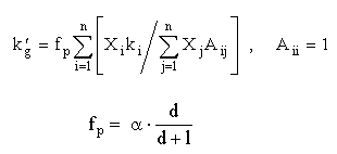
where ks is the thermal conductivity of the pure solid material,F the porosity, F'=F2/3, n the refractive index, B the extinction coefficient, s the Stefan-Boltzmann constant, and the gas mixture thermal conductivity, kg' ,can be evaluated by

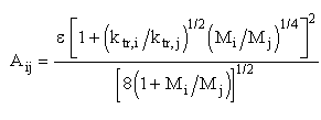
where a is the accommodation coefficient, d the pore diameter, l the mean free path, X the mole fraction. The effect of pressure on keff is accounted for by the factor fp in the above equations which takes into account both the molecule-to-molecule and molecule-to-wall collisions. The coefficient Aij are defined as

where M is molecular weight, ktr is the monatomic value of the thermal conductivity, and ƒÃ is an empirical constant. The detail on Aij can be found in Reid et al [8].
Modified Russell's equation is used for the conduction part. As shown in Fig. 2, this equation can explains very well the thermal conductivity of PUF under evacuated or normal pressure cases. It can be applied to predict the insulation performance of PUF under various conditions.
3. INSULATION PERFORMANCE OF LIQUID HYDROGEN STORAGE TANKS
The combined PUF and vacuum insulation system is studied as the insulation structure of large scale liquid hydrogen storage tanks. In this paper, only the conceptual design is discussed. The bottom part insulation is not discussed here. A vacuum insulation is applied, therefore the system has two tanks. The inner one is a liquid hydrogen storage tank and the outer one is a vacuum tank. The space between the inner and the outer tanks is the insulation space. In conventional design, PUF is set on the inner liquid hydrogen storage tank (we call it "inner PUF case"). In this study, the PUF is set on the inner side of the outer tank (we call it "outer PUF case"). In addition, we also study the case which uses a Vapor Cooled Shield(VCS) sometimes used in cryogenic tanks. Fig. 3 shows the structures of these insulation systems. Estimation of insulation performances is carried out by numerical calculation. In this calculation, resulting thermal conductivity of PUF and radiation heat transfer in vacuum space are used. The effect of VCS is expressed in terms of the enthalpy difference of vapor hydrogen at the VCS temperature and the inner tank temperature, and in decreasing the heat flux into the inner tank.
Fig. 4 shows the results of calculation and Fig. 5 shows the estimation results for hydrogen leak case. The following are observed.
(1)The outer PUF case shows higher performance than the inner PUF case when using the normal pressure case thermal conductivity data.
(2)These cases show almost same performance with the evacuated PUF thermal conductivity data.
(3)The inner PUF case has 3 times larger temperature difference in PUF than the outer PUF case, so the later has smaller thermal contraction and is less likely to crack.
(4)In the case of using VCS, thermal performance is quite improved.
(5)Reliable insulation performance can be maintained even in the hydrogen leak case. Closed-cell foam has merit against open-pore structure material or vacuum only insulation system in the event of hydrogen leak.
4. CONCLUSION
The thermal conductivity of PUF in practical condition is obtained, and thermal performance of several insulation configurations are estimated. As a result of this study, the mean thermal conductivity of evacuated PUF is about 7[mW/mK] in temperature range 20[K] to 300[K], which is 42% of normal pressure case. Thermal conductivity decreases with temperature, and it becomes 2[mW/mK] below 40[K]. Considering this property, the insulation configuration with higher performance than conventional configuration can be constructed.
It is concluded that the outer PUF case shows higher performance than the inner PUF case. Insulation system with VCS shows even higher performance. However, several items remain to be resolved and it is harder and more expensive to construct and maintain. The configuration without VCS can achieve the preset boil-off gas rate with simple design. Therefore, it will be used in future studies.
REFERENCES
[1] NEDO 1995 Year Report Vol.3, NEDO-WE-NET 9553 (1995)
[2] NEDO 1996 Year Report Vol.3, NEDO-WE-NET 9653 (1996)
[3] M.Yamaguchi et al., Cryogenic Engineering Conference, Columbus, OH (1995)
[4] C.J.Tseng et al., Proc. of 55th Meeting on Cryogenics and Superconductivity, p245 (1995)
[5] L.Sparks, P.B.Rep. PB85-10094 (1984)
[6] C.J.Tseng et al., Proc. of 34th National Heat Transfer Symposium of Japan, Vol.2, p413 (1997)
[7] C.J.Tseng et al., Cryogenics 37, p305-312 (1997)
[8] R.C.Reid et al., The Properties of Gases and Liquids, 4th ed, McGraw-Hill, Inc., New York (1987)
|